Monday, June 13, 2022

A farmyard tour

 From the beginning we'd had lots of ideas, but the practicality of most of them, while not beyond us, meant that just getting on and making a video was more time important. The venue was to be a garden, giving us three different surfaces very quickly, grass gravel and paving. Obstacles are easy to find, but they have to be ones which the robot can negotiate, so small steps are ok, garden tools etc. 

One thing we didn't have was something which would mean the robot would be able to climb higher than itself, so as the garden was hosting us, we decided to make something for the garden and constructed a bridge over the garden pond, "The Bridge of Pi's" out of reclaimed pallet wood. 


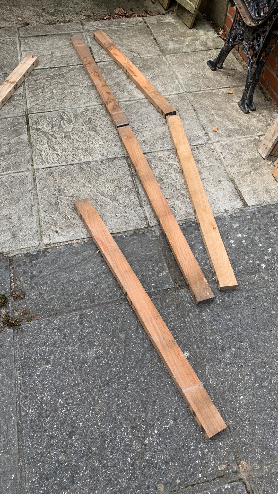
Not very 'robot like', but just the practicalities of making an interesting course. :)

Similarly, we needed a obstacle which the robot would have to manipulate before continuing, so for our video, we made a 'kissing gate', something which is very common on farmland to provide a pedestrian gate which can't be negotiated by animals but doesn't require closing. 

Again, reclaimed wood is used to build a simple and portable obstacle.


The robot enters via one side, moves the 'gate' to the other and then drives out. In practice the driving in proved to be the biggest problem!!!!


The rest of the challenge is populated with farm characters/animals and a few signs to give a 'tour' feel. The following pictures just give an idea of what it looked like and some of the features.


This is a view of the garden we were fortunate to use, driving round it twice used up our 5 minute video allowance! It had gravel, grass and paving to give us the required three surfaces, though in the end it had several more!!!

The video is linked here......East Devon PIrates

Starting from the beginning.....

The ticket office....
Mine host....sings Old MacDonald....

The Sheep Dip Seesaw....


Robot Restaurant...and for anyone who might recognise it, Hitchhikers Guide references.
Hungry Cattle Cafe.....most of the rice eaten
The Troll Bridge......

...and a better view
The Lamb Joint......

 Wolf Hall......

The World's Simplest Maze....


And for Indiana Jones fans.....see the video for how this worked out!!!!

Finally, a picture of the gardens owner sunbathing !!!!!


Sunday, June 12, 2022

Zyderbot Architecture

 Zyderbot is very modular and the parts have been assembled to work together around ideas put in place early on in the competition. This is a brief overview of what it comprises. 


The central chassis, as described in previous blogs. houses the controller Raspberry Pi and it is this which forms the central control and communication hub of the robot. 

A VNC connection to this Pi is used to connect to it from a laptop and programming is done using the Python IDE or Thonny. The controller Pi also runs the camera, support for which is built into the Pi.

The rest of the robot platform is modularised to provide dedicated functions, there are two groups, the main chassis controllers and the attachment controllers. As this is our first entry into PiWars, we've designed something which is reusable and the design and code is on Github. 

The main controller runs a command queue, onto which commands can be placed, either from an onboard file, as running a script, from the command line as direct input, or as a response from a separate controller, which in this case is either a Pico or an ESP32.

For autonomous processing, the controller reads a script file and runs commands to either take actions or invoke further autonomous actions, such as running a trough filling hopper or picking an apple. 

A motion command will be sent to the Motor Controller Pico which measures distance and actuates the four chassis motors. 

For Remote Control operation, an ESP32 is used with a PS3 handheld controller to submit commands to the controller, which are passed onto the Motor Controller, providing the necessary control.

For audio input, a separate Pico is used to listen on a microphone, interpret the audio signals it receives, and then pass these on to the command queue.

The Camera is invoked by commands to enable seeking and following operations, itself issuing commands back to the queue to act on received information.

The attachment controllers are there to enable easy integration between the chassis and the attachments, running all the attachment motors, servos and sensors so relieving the main controller of that burden and providing a division of labour.

For each PiWars challenge, an attachment is provided, to a standard mounting specification, power supplied from the batteries as a nominal 12V and communication to the Pi controller is over USB, which also supplies controller power an enables coding on the attachment controller from the central Pi.

There's a lot of code around this, as well as some direct handshake signals to get the timing right, but it's a good platform to take forward into future projects and competitions.

Wednesday, May 25, 2022

Toot Toot

 There's a bit of Shepherds Pi and the Farmyard Tour that gives points for audio control, so this is our take on it. This doesn't do much, listens for a whistle and then provides basic interpretation into commands. One whistle 'toot' is a command, as well as two and three, and after a brief interlude, the last command is cancelled. 


For this, a Pi pico is paired with a microphone....and a whistle...feeding the ADC of the pico with the audio signal, and then running an FFT against the signal to pick out the whistles' frequency, 2k7Hz in this case and converts blasts it into a logic signal.


As with the other attachments, this supports the WHOU enquiry, GPIO handshake and returns the info of TOOT, TOO2 and TOO3 as commands.  Power and serial comms are via USB for easy attachment.

Seems a bit of a small post, but it's a complete sub-project that contributes.


Monday, May 23, 2022

Using the remote

 With lots of challenging challenges, it has felt easy to ignore that the Farmyard Tours was to be remote control and not autonomous, so we needed a solution which was a bit more dextrous than a keyboard. Using a full RC set with adapters was always an option, but a more personal system was preferred and an almost universal games controller format was chosen. 


Could have been any brand, but it turned out as a low cost PS3 controller from a no-name Chinese source. As the main Pi controller just wanted a data feed it could translate, the interface chosen to the controller was Bluetooth run by a small ESP32 module dedicated to the communication. This was a lot less bother than direct comms and meant that the controller Pi wasn't cluttered with noisy code. Here is a larger dev board for testing, and mounted on a test chassis. The communication is via serial over USB and a simple handshaking option is used to request data from the PS3. 


One of the issues with this configuration is that when the controller times out and disconnects, the ESP32 code can't reconnect, so an extra pin was dedicated to reboot the ESP32 into connection mode again. 

Here's a brief video of the test chassis twirling in the arena..........and negotiating a bit of garden.


....and negotiating a bit of garden.


Thursday, May 19, 2022

A new chassis

So after lots of testing....well a bit anyway...we needed to build a new chassis, if only because we'd drilled so many holes in the old one! 

First make the battery holder which is also part of the suspension. Here it is.


Well that's spectacular isn't it. It's very basic, is made from a piece of acrylic tube, one end has a fixed plastic plug with a battery contact permanently attached and the other has a plastic spring holding the other contact in, which is held in place with a screw. The tube itself forms the central pivot of the suspension.

The two halves of the chassis were updated to accommodate the positioning of the camera as well as the main controller and attachment processors.

This is the rear subframe from below, the motors fixed in place either side of a tunnel which houses the battery tube. 

And a picture of the front subframe, housing motors, a camera and illumination LEDs, with the second half of the battery tunnel shown.

Putting them together, with an empty tube in the middle. The two subframes can rotate independently of each other around the battery tube. This isn't of much use in the arena challenges, but when negotiating the farm tour obstacle course it's expected to come into its own to keep the chassis stable and in contact with the ground.

As mentioned previously, part of the rebuild was to accommodate a camera.
The camera is mounted below the attachment deck of the chassis, the bolt holes for attachments can be see top left and right, and faces down and forward, looking at the arena surface ahead of the robot. The LEDs are there to ensure it has plenty of illumination for the camera and isn't dependent on ambient light, eliminating an uncertain variable.


Close-up of the two subframes partly rotated against each other to show the suspension in operation. Already, with only the motor, LEDs and camera fitted there are a lot of wires in this robot and cable management is important, hence the prepared holes in the subframes.

From the outset we wanted interchangeable wheels to adapt to the different challenges. These are 'arena' wheels with their adapters. The adapters were always part of the design as with so many different motor shaft attachments available we needed to be able to switch them without having to remake whole wheels.


Now it looks a lot more like something with the wheels attached and wires routed. The front chassis  mounts for attachments can be seen, and that growing wiring is getting some management..

And suddenly there's a wire explosion!!! At the rear (right) is the main power switch, and just ahead is the controller pi board mounted vertically. At the far side is the power regulator. Raw power from the batteries is delivered at around 11V and used by the attachments, the regulator ensures the pi is supplied with a healthy 5V. 
Nearest the camera is the motor control pico which receives commands from the controller and incorporates a LED to provide a simple status display. This connects to the controller via USB. 

And here is the assembled new chassis with the Hungry Cattle hopper attachment. 
There's a lot of parts to this but it does work very well. Only a short video of this chassis working but it gives an idea of the basics.


Next up a  blog giving a description of the architecture of these robots.


Thursday, March 17, 2022

Attachment action

After a bit of a delay actually doing things, now entering the phase of actually testing some solutions. 

First up is the Shepherds Pi herding solution. The chassis is working well and to get the basic herder fitted just required some bolts, power and a USB cable. This wasn't just a sudden event and the interface has undergone a bit of refinement.


What looks to be the final interface is to run attachment microcontrollers from USB via a hub, with a separate power supply to run motors and servos, putting the power conversion on the attachment to optimise for the particular attachment, standard power supplied being 12V.


This is a picture of the shepherding attachment, controlled by a Pico on a Kitronik control board connected to the arm servos with a small buck converter power supply and power display. Also shown is a handle to aid picking the chassis up as it's now getting a significant amount of handling. The control board is a bit over specified here but in the next iteration will have to run two stepper motors.

The shepherding attachment has gone through several phases, and the one shown is good enough for basic positional testing using dead reckoning. Here's a video of a basic operation.


Some erratic movement on the arms due to controller initialisation signals, but this is a good test of a sheep 'fetch'.

While the arms do a good job with the sheep, they do need to do more and so the turbo-shepherd version is in construction and testing. Here's a video of it in test mode. 


Here a stepper motor is now giving lift to the arm to allow it to be move up and out of the way, open and close the gate, as well as potentially pick up recalcitrant sheep!

With the herding going well, the Hungry Cattle challenge is almost complete.

The montage above shows the feed dispenser attached to the chassis. The feed hoppers are attached to a turntable mounted between the wheels of the chassis. The robot feeder drives up alongside a trough, the turntable rotates a full hopper over the trough and dispenses feed. The robot then moves on to the next trough, meanwhile the hopper rotates the next hopper into position. Once feeding complete, the hopper turntable rotates back to a central position for refilling. The controller here is a Pico on a dedicated bit of stripboard to run three servos and a small stepper. 

Finally, a bit of dimension checking. The rules say it all has to fit withing the marked rectangles, so here we are, fitting in!
Picture with arms extended

and then with arms parked.
May need to tidy a few wires up!!!! 

That's it until next time, when we'll have some remote control via a PS3 controller, a dog whistle and maybe even some voice commands.....come by Shep!


Friday, February 25, 2022

Joining bits together!

Another team meeting this week to look at where we're going and show our progress. This is more a position update blog, not much to show in a structured way but an example of where we are.


First up is a video of the sheep herder. This is the basic version in operation, not the turbo, just giving us a view of how things will pan out in the arena. The arms and flippers aren't powered and dead reckoning is used for the small amount of navigation shown.


So we have a sheep dog but it needs a bit of training! This is also the first time a chassis and attachment have been mated together, it took only a few minutes and that's how the other attachments should fit!

Also demonstrated was our change to the use of a PS3 controller for remote control operations. We'll be using this for the Farmyard Tour challenge of course but it's main job in the coming weeks is to rehearse the best sequence of operations for the chassis and attachments for testing.

We're still moving on with the apple picking attachment, the laser cut practise tree shown in the last blog entry is now assembled, needs a bit of weight adding and the apple picking cup MK2 ready for testing.


Finally the cattle feeding turntable was demonstrated. This challenge is almost ready for full testing with most of the components finalised and control code written. This is possibly the simplest attachment but still comprises 36 individual 3D printed parts, together with many nuts, bolts, servo's and a stepper motor. Hidden in there is the custom controller board as well!


The picture has been shown before but next time will be a full demo video, we've already written the routine for the video!. Its controlled via micropython on a pico. 


That's it for this time, next time we'll have working sheep dog arms and a trough filling attachment!


Tuesday, February 15, 2022

High Speed Hoppers, bit of apple picking and some scary sheep handlers

The Hungry Cattle solution is still going well and we now have three hoppers mounted on a turntable which reside withing the wheel base when fully loaded, but can selectively swing out to dump their feed into a trough, either at the front of the robot or to the side.

This is the 'closed' position with the weight centralised. This isn't the competition chassis, just the test one.


And then its swung round to place a hopper over a trough at the side, and also at the front if that is advantageous.

New hopper funnels are being made to throw the feed further and try to get a more even spread in the trough, and hold a bit more feed to ensure coverage.

The turntable is run on a small stepper motor but there isn't any synchronisation fitted yet so it a bit hit and miss as to where it stops. Here's a video of it rotating.


Once synchronised, the hopper will rotate in 90 degree steps. When the hopper stops over a trough, the hopper releases it's feed using the drum mechanism and the robot can move on to the next trough. The hoppers rotate back to the inboard position for refilling.

Not a lot of news published on the apple picking. Here we have one of the apple pickers and a tree worthy of Ikea, laser cut from 3mm ply.


Scary carpet eh?


The turbo-shepherd has had the first iteration of the sheep handling arms tested.


This hasn't been that successful but the idea is working ok. To improve its operation, more powerful servo motors will be chosen and the layout of the components optimised to be able to 'herd' the sheep more effectively. The video shows the arms being parked, open wide to gather sheep, and also selectively moving to push sheep to the side. The movement could be a lot faster and smoother but this is primarily to test the concepts.

Here is the updated design being built.


The challenge has been to loose as much of the mechanism in height rather than loose herding capacity, the parked position being less than 225mm wide and 100mm deep, and folding out to 325mm wide to gather the sheep. before pushing them into the sheep pen. The arms will also operate the gate mechanism.

Next up, hopefully first views of the apple picker, completing the Hungry Cattle hardware and maybe a bit more of the sheep handler design built. On a personal note, I'm just pleased RS components delivered my reel of solder today :)  


Saturday, February 12, 2022

Start of an arena

 While a lot is happening, somehow there's never much to see for all the effort, but at our last PiWars get together we had the start of our arena to view.


It's made out of flooring board so can be dismantled into three parts and we've marked it out in 250mm squares to start getting the feel for what the space looks like.  No apple tree on view, but some test cardboard sheep and wolves, together with our newly made cattle troughs, fill up the space. 

It was also an opportunity to look at motor speeds and load capacity. This robot is our test bed for a set of four brushless motors. We've loaded it up at the front with a 1kg weight to simulate a full load of cattle feed (rice) to see what its performance is.


So speed tests put the crossing of the arena from standing start to stop at 2 seconds with the full load, which we're happy with. None of the attachments are very heavy so we're ok to go. Might need a bit more grip on the wheels to get better acceleration and ensure a skid free stop, but the work we described in the last blog has paid off, so success. A small accident in control during one of the tests demonstrated it also turns very quickly as well!

Also on demonstration on the arena are the navigation beacons.


These will be used by the vision cameras on the robot chassis to give an accurate position within the arena and provide the navigation references. This picture shows three coded beacons but the arena will be surrounded by them eventually.

As well as the tea and biscuits, a quick view of the kitchen table gives an overview of what's been going on.


In the foreground on the far left is the time synchronisation test rig to provide an accurate common time reference to the independent stereo cameras.

Beside it in yellow and black, is the modified cattle feed hopper, extended at the top to hold more feed, and fitted with a large drum to deliver feed to the trough faster. Also shown are two other hoppers in green with out the capacity extension. The need for the extension followed tests with the accurate 3D printed troughs showed that we hadn't been delivering enough feed to the trough to cover the centre line so we needed to increase the amount. We could have designed some sort of shaking device to even out the feed in the trough but just increasing the amount was faster and unsophisticated.

Between the two green hoppers is the new turntable to rotate hoppers over the side of the robot chassis for dispensing, and then returning them to an inboard position to keep the weight distribution within the robot wheels.

At the rear is a yellow test robot chassis powered by an ESP32 which is used to test attachments and in front of that a pair of arms for gathering and gripping sheep. We found that the cardboard sheep we'd made were actually to big and so the arms couldn't quite reach round them! It also used fairly low cost servos which didn't perform well, so will need a bit of an upgrade before the next demonstration, as well as the lift mechanisms fitting with the new stepper motors.

Next meet will be a test of the Hungry Cattle challenge with remote control, progress! 

Finally just another picture of the arena with bits in place. We had made three wolves and six sheep but two sheep were lost, but we put them in place anyway.


Also on show are the beacons, troughs, stereo cameras, and four test bed chassis!!!!!

Tuesday, February 1, 2022

A New Chassis, new motors and fancy troughs

 So we've been designing a new chassis, based partly on the original, but with a few new ideas added. 


The coffee and biscuits are a key part of the design process though may not be part of the final implementation. These are HLC208 encapsulated brushless motors with the controller electronics built-in. They also have their own direction selection feed as well as an accurate speed output. 

The supplier website gave instructions for testing these out and some sample code, but that did little other than turn the motor. Adding an extra earth and scrapping their example code in favour of hastily written test code got them working nicely, variable speed, direction changes and feedback with very little cpu time involved. Very simple to use when you know how!!!! We'll see how they progress.

Now that we have some stl files for the Hungry Cattle troughs from the organisers, we thought investing some print time in creating three accurate troughs with halfway lines printed in. And here they are, they look ok, though we did get one line not quite right!! So just have to fill to above the line!


Next up will be the new hopper emptying mechanism, should be a bit faster than last time.