So after lots of testing....well a bit anyway...we needed to build a new chassis, if only because we'd drilled so many holes in the old one!
First make the battery holder which is also part of the suspension. Here it is.
Well that's spectacular isn't it. It's very basic, is made from a piece of acrylic tube, one end has a fixed plastic plug with a battery contact permanently attached and the other has a plastic spring holding the other contact in, which is held in place with a screw. The tube itself forms the central pivot of the suspension.
The two halves of the chassis were updated to accommodate the positioning of the camera as well as the main controller and attachment processors.
This is the rear subframe from below, the motors fixed in place either side of a tunnel which houses the battery tube.
And a picture of the front subframe, housing motors, a camera and illumination LEDs, with the second half of the battery tunnel shown.
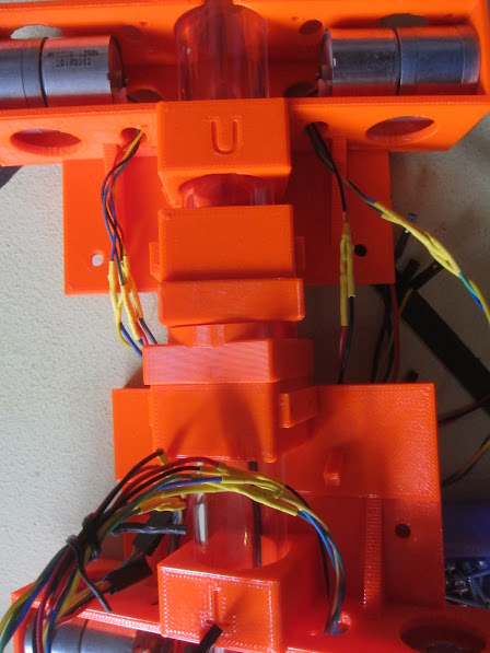
Putting them together, with an empty tube in the middle. The two subframes can rotate independently of each other around the battery tube. This isn't of much use in the arena challenges, but when negotiating the farm tour obstacle course it's expected to come into its own to keep the chassis stable and in contact with the ground.
As mentioned previously, part of the rebuild was to accommodate a camera.
The camera is mounted below the attachment deck of the chassis, the bolt holes for attachments can be see top left and right, and faces down and forward, looking at the arena surface ahead of the robot. The LEDs are there to ensure it has plenty of illumination for the camera and isn't dependent on ambient light, eliminating an uncertain variable.
Close-up of the two subframes partly rotated against each other to show the suspension in operation. Already, with only the motor, LEDs and camera fitted there are a lot of wires in this robot and cable management is important, hence the prepared holes in the subframes.
From the outset we wanted interchangeable wheels to adapt to the different challenges. These are 'arena' wheels with their adapters. The adapters were always part of the design as with so many different motor shaft attachments available we needed to be able to switch them without having to remake whole wheels.
Now it looks a lot more like something with the wheels attached and wires routed. The front chassis mounts for attachments can be seen, and that growing wiring is getting some management..
And suddenly there's a wire explosion!!! At the rear (right) is the main power switch, and just ahead is the controller pi board mounted vertically. At the far side is the power regulator. Raw power from the batteries is delivered at around 11V and used by the attachments, the regulator ensures the pi is supplied with a healthy 5V.
Nearest the camera is the motor control pico which receives commands from the controller and incorporates a LED to provide a simple status display. This connects to the controller via USB.
And here is the assembled new chassis with the Hungry Cattle hopper attachment.
There's a lot of parts to this but it does work very well. Only a short video of this chassis working but it gives an idea of the basics.
Next up a blog giving a description of the architecture of these robots.


No comments:
Post a Comment