Doesn't say 'could do better' but next time!!!!
Final blog entry for this year. We got four videos created, and the blog, but failed on the Natures Bounty video.
Most of a sophisticated apple picker was built, but not enough to be ready for using in a videoed challenge.

We did try to rustle up an alternative in the last few hours which basically knocked the apples off but time just ran out, and we concentrated on delivering what we could do. Disappointing, but our first try at the competition and we've learnt a bit in the process.


It'll be fun seeing what everyone else has done, but not sure we'll get away with doing it again, just a bit to much time.
Still, next up is Sidmouth Science festival, when we'll have a lot more robots wandering about. Think that's where we came in!!!!
East Devon Pirates
Just a brief post to show our video recording area....it's actually a bedroom with the arena laid on top of the bed.

We moved here from the kitchen floor due to other people needing to use the kitchen for space and we can use this all day without being trodden on!!!
The camera is mounted on a tripod to the right and to the left is a table to sit with laptop for robot set up, in this case with the next variation on out sheep herder, in this case a very much more 'beefed up' version made up from recycled robot arms.....and Lego!
From the beginning we'd had lots of ideas, but the practicality of most of them, while not beyond us, meant that just getting on and making a video was more time important. The venue was to be a garden, giving us three different surfaces very quickly, grass gravel and paving. Obstacles are easy to find, but they have to be ones which the robot can negotiate, so small steps are ok, garden tools etc.
One thing we didn't have was something which would mean the robot would be able to climb higher than itself, so as the garden was hosting us, we decided to make something for the garden and constructed a bridge over the garden pond, "The Bridge of Pi's" out of reclaimed pallet wood.
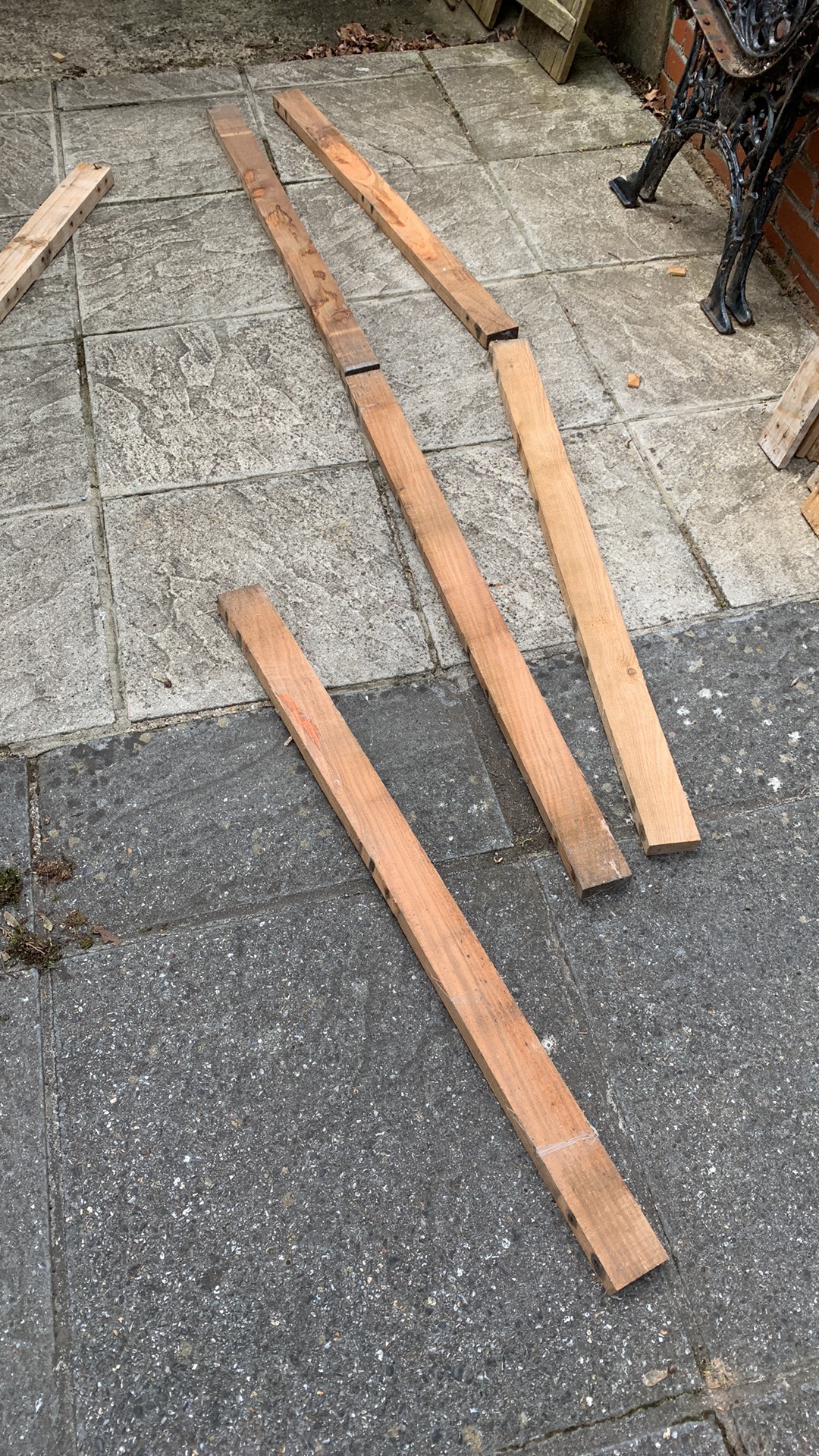


Not very 'robot like', but just the practicalities of making an interesting course. :)
Similarly, we needed a obstacle which the robot would have to manipulate before continuing, so for our video, we made a 'kissing gate', something which is very common on farmland to provide a pedestrian gate which can't be negotiated by animals but doesn't require closing.
Again, reclaimed wood is used to build a simple and portable obstacle.


The robot enters via one side, moves the 'gate' to the other and then drives out. In practice the driving in proved to be the biggest problem!!!!
The rest of the challenge is populated with farm characters/animals and a few signs to give a 'tour' feel. The following pictures just give an idea of what it looked like and some of the features.

This is a view of the garden we were fortunate to use, driving round it twice used up our 5 minute video allowance! It had gravel, grass and paving to give us the required three surfaces, though in the end it had several more!!!
The video is linked here......East Devon PIrates
Starting from the beginning.....


The Lamb Joint......

Wolf Hall......

The World's Simplest Maze....


Zyderbot is very modular and the parts have been assembled to work together around ideas put in place early on in the competition. This is a brief overview of what it comprises.

The central chassis, as described in previous blogs. houses the controller Raspberry Pi and it is this which forms the central control and communication hub of the robot.
A VNC connection to this Pi is used to connect to it from a laptop and programming is done using the Python IDE or Thonny. The controller Pi also runs the camera, support for which is built into the Pi.
The rest of the robot platform is modularised to provide dedicated functions, there are two groups, the main chassis controllers and the attachment controllers. As this is our first entry into PiWars, we've designed something which is reusable and the design and code is on Github.
The main controller runs a command queue, onto which commands can be placed, either from an onboard file, as running a script, from the command line as direct input, or as a response from a separate controller, which in this case is either a Pico or an ESP32.
For autonomous processing, the controller reads a script file and runs commands to either take actions or invoke further autonomous actions, such as running a trough filling hopper or picking an apple.
A motion command will be sent to the Motor Controller Pico which measures distance and actuates the four chassis motors.
For Remote Control operation, an ESP32 is used with a PS3 handheld controller to submit commands to the controller, which are passed onto the Motor Controller, providing the necessary control.
For audio input, a separate Pico is used to listen on a microphone, interpret the audio signals it receives, and then pass these on to the command queue.
The Camera is invoked by commands to enable seeking and following operations, itself issuing commands back to the queue to act on received information.
The attachment controllers are there to enable easy integration between the chassis and the attachments, running all the attachment motors, servos and sensors so relieving the main controller of that burden and providing a division of labour.
For each PiWars challenge, an attachment is provided, to a standard mounting specification, power supplied from the batteries as a nominal 12V and communication to the Pi controller is over USB, which also supplies controller power an enables coding on the attachment controller from the central Pi.
There's a lot of code around this, as well as some direct handshake signals to get the timing right, but it's a good platform to take forward into future projects and competitions.
There's a bit of Shepherds Pi and the Farmyard Tour that gives points for audio control, so this is our take on it. This doesn't do much, listens for a whistle and then provides basic interpretation into commands. One whistle 'toot' is a command, as well as two and three, and after a brief interlude, the last command is cancelled.

For this, a Pi pico is paired with a microphone....and a whistle...feeding the ADC of the pico with the audio signal, and then running an FFT against the signal to pick out the whistles' frequency, 2k7Hz in this case and converts blasts it into a logic signal.

As with the other attachments, this supports the WHOU enquiry, GPIO handshake and returns the info of TOOT, TOO2 and TOO3 as commands. Power and serial comms are via USB for easy attachment.
Seems a bit of a small post, but it's a complete sub-project that contributes.
With lots of challenging challenges, it has felt easy to ignore that the Farmyard Tours was to be remote control and not autonomous, so we needed a solution which was a bit more dextrous than a keyboard. Using a full RC set with adapters was always an option, but a more personal system was preferred and an almost universal games controller format was chosen.

Could have been any brand, but it turned out as a low cost PS3 controller from a no-name Chinese source. As the main Pi controller just wanted a data feed it could translate, the interface chosen to the controller was Bluetooth run by a small ESP32 module dedicated to the communication. This was a lot less bother than direct comms and meant that the controller Pi wasn't cluttered with noisy code. Here is a larger dev board for testing, and mounted on a test chassis. The communication is via serial over USB and a simple handshaking option is used to request data from the PS3.


So after lots of testing....well a bit anyway...we needed to build a new chassis, if only because we'd drilled so many holes in the old one!
First make the battery holder which is also part of the suspension. Here it is.

Well that's spectacular isn't it. It's very basic, is made from a piece of acrylic tube, one end has a fixed plastic plug with a battery contact permanently attached and the other has a plastic spring holding the other contact in, which is held in place with a screw. The tube itself forms the central pivot of the suspension.
The two halves of the chassis were updated to accommodate the positioning of the camera as well as the main controller and attachment processors.


After a bit of a delay actually doing things, now entering the phase of actually testing some solutions.
First up is the Shepherds Pi herding solution. The chassis is working well and to get the basic herder fitted just required some bolts, power and a USB cable. This wasn't just a sudden event and the interface has undergone a bit of refinement.

What looks to be the final interface is to run attachment microcontrollers from USB via a hub, with a separate power supply to run motors and servos, putting the power conversion on the attachment to optimise for the particular attachment, standard power supplied being 12V.

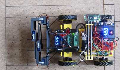
This is a picture of the shepherding attachment, controlled by a Pico on a Kitronik control board connected to the arm servos with a small buck converter power supply and power display. Also shown is a handle to aid picking the chassis up as it's now getting a significant amount of handling. The control board is a bit over specified here but in the next iteration will have to run two stepper motors.
The shepherding attachment has gone through several phases, and the one shown is good enough for basic positional testing using dead reckoning. Here's a video of a basic operation.
Some erratic movement on the arms due to controller initialisation signals, but this is a good test of a sheep 'fetch'.
While the arms do a good job with the sheep, they do need to do more and so the turbo-shepherd version is in construction and testing. Here's a video of it in test mode.
Here a stepper motor is now giving lift to the arm to allow it to be move up and out of the way, open and close the gate, as well as potentially pick up recalcitrant sheep!
With the herding going well, the Hungry Cattle challenge is almost complete.