Showing posts with label Chassis. Show all posts

Saturday, December 9, 2023

Minesweeper - PiWars 2024

The Challenge

The Minesweeper challenge requires the competing robot to reposition itself  to one of sixteen squares in a 4x4 matrix when that square is illuminated as red from the normal white. Covering any part of the square with the robot counts as covering it. and thus mine found. Once the robot has remained over a square for one second, then another square is randomly selected and illuminated, to which the robot must move next.


A total of 20 squares can be illuminated for each robots run and a run ends after either 5 minutes or all 20 mines have been found. If all 20 are found then the time taken to complete the run is recorded and points awarded to the robot according to the formula system

There are points awarded for each square found, 50 for autonomous robots and 35 for remote controlled robots. All competitors get 150 points extra for finding more than 10 mines. Just for competing, autonomous robots get 250 points, so entering as autonomous is worthwhile even if the robot can only move briefly. There are therefore a total of 1550 points available for autonomous robots and 1300 for remote controlled robots.

Analysis

Using conventional wheels driving to a square will require first steering, and then driving. Using tank steering this would be a simple manoeuvrer, but with Akerman steering this could become more complex and in the confines of the 4x4 matrix more longwinded. The use of mecanum or omnidirectional wheels would make moving to a square more direct as the robot only has to set the drive parameters to move in the correct direction. Sticking to the intersections would mean that the robot would only have to move the minimum distance to succeed in finding a square and also covering the central intersection equally as effective. 

For remote control and autonomous robots, once a robot has gained an aligned position over an intersection, instead of analogue steering, commands could be to move 400mm on the required vector simplifying actions and potentially making the robot more reliable.

Each square is 400mm on each side so a robot positioned on an intersection could cover four squares. With a random selection, if a robot can get itself parked on one of these intersections then there is a 1 in 4 chance that the next illuminated square is already covered. A not unreasonable tactic for an autonomous robot is to drive between these intersection points in a circular motion, stopping when it's detected that a square is illuminated. This could be a slightly more complex line following algorithm, ignoring other lines and stopping when the colour change is detected. This strategy would assist any type of steering. If it takes a robot 10 seconds to do a circuit of the squares, 3.2m, it might be expected to complete all 20 squares in less than 100 seconds.

Detecting a red square versus a white square for autonomous robots is a matter of both detecting the red and it's position. If the action of the robot is to actively search for the red, as in the intersection follower above, then the mechanism is built into the movement and detectors built into the corners of the robot might be expected to be enough. 

The detector above will give a precise colour measurement. Simpler detectors could be devised, with say an LDR covered with a green or blue coloured filter, and would give a good signal and no signal if over white or red, dodging the black lines as it goes!  A one minute calibration period is allowed for each robot before each competitive run to allow for adjustments so any detector can be optimised. 

Using this method also needs the dimensions of the robot taking into account and the detectors may need to be a permanent feature of the robot.

A popular choice may be a colour camera which can be used in simple or complex ways. Again, deploying a separate camera to the corners may be an effective way of determining the position of the red square when the robot passes over it, though may be more complex than imagined. Mounting a camera in a single line of vision would require the robot to reposition itself to find a red square, and then drive the robot to locate it. This may be effective but also time consuming as the robot searches and illuminated squares close to the robot may be difficult to see. Placing the camera on a rotating platform may help, though some additional engineering may be required, but would speed the process as only the camera would have to be used to locate a red square and a tilt mechanism could be used to view squares close by. 


Placing a camera high above the robot would give a better overall view of the arena and thus make the task of finding an illuminated square easier. If this camera were also a wide angle camera and positioned pointing straight down, then it could feasibly observe the whole of the arena and thus detect a lit red square without movement. For a robot navigating to a square using this camera method the task is easier because all that is required is that the navigation moves the red square as close to the centre of the cameras view as possible.

 If mounting the camera above the robot doesn't give an adequate view, or the camera angle isn't wide enough, the camera could be mounted on the top of the robot pointing upwards towards either a  plain or convex mirror. 

These are just a few ideas for solving this challenge, not sure which we'll use yet but the camera and mirror might be easiest, we'll just see what we do and might come up with another idea.

Update Meeting - PiWars 2024

 We finally all got together in the same room to see what we'd been up to. The big attraction of the afternoon was the Zombie Apocalypse challenge and where we'd gone with it so far.

This is very much in two parts, the gun platform and the gun.


Here we see the a mock-up of the gun, using parts removed from a working Nerf gun, and 3D printed parts to adapt them to test usage.


For the demonstration, the flywheel motor was driven by a switched AA battery pack (actually a 6 x AA pack adapted for 4 x AA) and the 'firing mechanism' is an SG90 servo connected to a servo tester.


As this mock-up shows, it works well. To get a feel for what the targets might look like, we have to practice, a few small pictures mocked up onto a cupboard helps. This is a view from the turret camera.


They look a bit small don't they! This was with a Pi Zero fitted camera, but a little upgrade helped.

This helped a lot!!!


The chassis has undergone a few changes as well, and now has a Pi3 inside, as well as the original wiring. The following picture shows what we've fitted inside.


This has meant that for operational testing the chassis has been modified further to get access to the boards inside, both to change the SD cards and to plug in USB cables. 


We also have headlights as well which will be very useful for the Lava Palaver challenge when consistent lighting will be important. Here's a video of the chassis in action.

This also demonstrates the control from a standard RC handset via SBus which is working well.

We have been active on building the Line Follower but that demonstration we'll leave until the next meeting.


Monday, November 13, 2023

Nerf Gun Platform - PiWars 2024

      In a team, items come along all the time and if you're writing the blog then either you leave a mountain of things to add, or just publish them there and then. 

     Some things just get decided as the obvious way to go so building a platform for aiming and firing a Nerf gun just seemed the sensible thing to do for the Zombie Apocalypse challenge, though there'll be a blog analysis of it along soon.

Mounted on the rear lid of the chassis, the arm is rather overkill to support a Nerf gun, but it has it's origins in one cooked earlier for a drawing robot arm, so easier than developing a whole new arm. The servos are AX12 serial servos controlled via the official Dynamixel USB controller by a Pi Zero, which can be just seen mounted under the arm, with camera for aiming. The gun connector is a Picatinny rail, Nerf fans will appreciate that.

The heart of the arm is this bearing. It weighs 220gms just on its own without the rest of the arm, but gives superb glitch-free smooth rotation with any weight, even unbalanced.

The whole truck now weighs 2Kg, but it still drives OK

The Nerf gun we are intending to use is a Nerf Stryfe which may not be available in shops any longer, but we have one because we like playing with things. NOTE: this is different to many of the newer versions of the electric Nerf guns in that it is screwed together and so can be disassembled easily, some of  the newer ones are glued together so much more easily damaged when being taken apart, possibly a job for a Dremel if using one.

The following pictures are of the gun mechanism.

Electric motors spin up flywheels just before the barrel of the gun and after the Nerf dart magazine. 

Once the flywheels are up to speed, the trigger is pulled and a mechanism pushes a dart forwards from the magazine, see the arrow in the picture above, until it is caught by the spinning flywheels which catch hold of it and accelerate the dart out of the gun barrel. The flywheel motors are designed to be run by four 1.5V alkaline batteries (about 15Wh) and are normally expected to not last long, but powering them from the vehicle batteries (31Wh) is expected to be ok for the challenge. 
A test cradle has been designed to hold the active portion of the Nerf gun and dart magazine to facilitate fitting to the aiming mechanism.

Out of the box, these foam dart guns have a surprising range and accurate over short distances so are worth the effort to modify. In the unmodified versions, the flywheels are only powered when a trigger switch is pulled, connecting the batteries, so are unlikely to be operated for long periods of time, this is an area which needs to be understood in order to ensure the reliability of the mechanism and prevent overheating. Of course, if the mechanism is going to be modded, increasing the voltage, and thus the speed of the flywheels, might increase the accuracy, something to experiment with. The mechanism also has a variety of interlocks to prevent operation when the gun is not complete, all of which will need to be removed or bypassed.

So, on with the fun, though it might be a bit longer before the next blog post!!!!

Saturday, November 11, 2023

Chassis development - PiWars 2024

 So we needed a chassis and while we had previous skeleton chassis we could have gone back to, one of us has been developing a more substantial bit of kit.

It started out as a four wheel drive 'tonka toy' with big rubber tyres that can handle uneven surfaces. As originally made, it looked a bit blank in lemon yellow, but a bit of paint for windows and a load to carry it looked a bit better. The chassis is in two halves, articulated in the middle, around a central battery holder for three 18650 LiPo's in series. 


The video shows a basic try-out though not very exciting. The remote control is via a helicopter RC and converted from SBUS via a Pico PIO program, code on github here EastDevonPirates2024. The voltage display on the rear, as well as an obvious on/off switch, are very useful.


But never quite happy, it wasn't really up to our PiWars 2024 standard,  so it's been remodelled. The wheels are much smaller to accommodate PiWars chassis size rules, they may change yet again but these are the working wheels for now.


Gone are the flashy headlights and a new detachable bonnet fitted to cover the remodelled battery box. 


We haven't remodelled the wiring yet, but we do have a flashy invisibility cloak (lid) so you can't see them!!! As well as being a lid, that will also be a platform for attachments, more on those in later blogs.


All that's in there right now is a Pico and an RC receiver. Independent FIT0441 brushless motors on each wheel with built in motor controllers and pulse counting for rotation sensing provide the driving force.

Fans of this look can get the stl files from github.


Thursday, October 26, 2023

Eco-Disaster PiWars 2024


 Something  to think about anyway, sorting 12 barrels by colour into two areas, autonomously, within 5 minutes. That's the PiWars 2024 Eco-Disaster Challenge detailed here Eco-Disaster – Pi Wars
Well we have to think about it, though we may never get to do it!!!

The Challenge

   The arena for this challenge is 2.2m square, with a central area of 1.6m square where the barrels are located, positions of which revealed on the day. 

    So, the challenge is to relocate the barrels, red for toxic, green for ok, to two areas, denoted as blue and yellow, scoring 80 points for the number of barrels relocated correctly, but loosing 40 points for incorrectly relocating barrels. There are extra points for part way completion, 50 for six barrels correctly sorted, and 150 for 12 barrels correctly sorted. Additionally, 250 points for completing the challenge autonomously, which as an 'advanced' team, we have to. As with other challenges where time matters, if all barrels are collected, additional points are awarded according to the formula system described here Formula Scoring System – Pi Wars. Thus, for completing the challenge correctly, and fastest, within 5 minutes this challenge scores 1510 points.


Approaches

   Here are three general approaches to the challenge, and the final one used may be one selected on the day depending on the layout of the barrels, or just a  mixture, but without a strategy then attachments can't be designed.

   As an alternative view, it's been pointed out that as an autonomous challenge earns 250 points, simply letting the robot stand still or spin on the spot might earn the points, as incorrect barrel placement, however accidental, will loose points.

   Assuming we're actually going to attempt the challenges, the first hurdle is identifying the colour of the barrels to be placed. An immediate option is a colour camera which has associated code to identify the colour correctly. If this is used then it's likely that this camera will also be used for navigation to the clean and contaminated zones, and preferably avoiding knocking over any of the other barrels.


      A less code intensive option is to use a colour sensor such as a TCS230, which can be tuned to identify the correct zone and barrel colours on the day. This would have to be used in association with a separate navigation system, such as an ultrasonic, laser or IR system. 


1. Individual Barrel Placement

    This requires that the robot locate each barrel, identify the colour, and then navigate across the arena to the correct location and place the barrel there. 

    At it's most basic, the robot could be fitted with a 'pusher', drive up to the barrel, push it around the arena and into its correct zone, then repeat 11 times. This does imply that the route to the zone is navigable and also that the barrel is in a position to be pushed, and hasn't been stuck up against a wall.

    The next step to this would be to have a barrel handler which will grip the barrel in some way allowing the barrel to be positioned where required. Attachment design ideas are in a later section.

   The arena design has allowed for free movement around the outside initially and a simpler strategy might be to drive the robot to one of the corners adjacent to the target zones and collect the barrels from that position where the other barrels would be unlikely to get in the way of a robot repositioning one.


2. Sweep Then Sort

   In this strategy, the robot makes two passes at barrel placement. 

   In the first pass, the robot uses a pusher, possibly of maximum width 325mm, to push all the barrels collectively  to the side of the arena containing the zones. This will immediately place some barrels in the correct zone and of course some in the incorrect zone, as well as a few outside a zone. This may appear to be a quick solution but it would probably take five passes over the arena to guarantee collecting all in this way which might reasonably take 1 minute. 

   In the second pass, the robot then begins to sort the barrels, now against  one arena wall, either moving an incorrectly placed barrel to the correct zone, or simply passing over a barrel if already correctly placed. A basic system would be to work from right to left, or left to right, checking each barrel and moving each errant barrel when found. Moving barrels at this stage could be using a similar push/grab attachment as in approach 1, or a specialised sideways grabber to allow a robot to drive back and forth along the line of barrels. A slightly more advanced approach would be to scan all the barrels for position, possibly while relocating one, and then shuffle a barrel in error from the other zone back until all barrels are correctly placed. Barrels not in a zone must be identified and moved into a zone, as well as the correct zone.

   On a points basis, if a robot autonomously ploughed all barrels into one zone, it would score 540 points, so as a default position this strategy has some advantages. From then on, every barrel moved to it's correct zone effectively gains the robot 120 points, plus the bonus if all barrels correctly positioned.

3. Collect and Deliver

   This approach requires that the robot be capable of sorting and moving all or many, barrels at once.

   The robot drives around the arena collecting barrels, and once it's collecting capacity is full, drives to the zones to deposit the collected barrels. This could take one of several routes.

  1. The robot collects all, or several, of one colour and takes them to the appropriate zone.
  2. The robot collects all, or several, of any colour and takes them to the appropriate zones, sorting them as they are deposited.
  3. The robot collects and sorts all, or several, barrels of any colour and deposits them in the appropriate zones.

   This could obviously require an attachment not much more complicated than that used in approaches 1 and 2, or could involve something more complicated where up to 12 barrels are sorted and moved by a robot at once.

Attachment Ideas

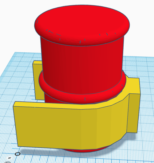
    At it's most basic, a successful pushing attachment only has to sufficiently enclose and support a barrel at a low level to enable it to be positioned into a zone. This attachment could also include a colour identification sensor. 


Basic Pushing Attachment

    A pushing attachment has its limitations not being able to pull for which some sort of grabbing/gripping mechanism is needed. This can take the form of a passive grab (say a simple push doorway mechanism), and an active release, or an active grab and release, but given the low weight of the barrels, a passive grab may have limited use.

Upgrading the basic idea with a servo and a hinged flap...


   This now offers both push and pull from a simple grab, the servo can also be used to open the flap to give a bigger area to capture a barrel. 
Extended capture position, rounding off the edges a bit will probably help with capture.

   To handle the collection of multiple barrels and herding them to one place or another, as per approaches 2 and 3, something a little larger would be needed. No attempts here at loading a hopper or any other container, but that would definitely be a good option for anyone with design imagination and lots of time.  
   The flaps extend to accommodate and shepherd more barrels into the holder. they would fold flat at the beginning of the challenge to be extended. While they couldn't go wider than 325mm, they could extend to say 150mm forward so accommodating three rows of barrels.


With all barrels present


And this view begins to look like a server at Oktoberfest

These last two are simple horns to collect the barrels in two sections

The robot would have to plot its course to ensure it could easily collect and deposit mixed loads.
 
   We'll have to see what approach we'll take, we've built approach 2 before, but we may have a combined idea completely different. 
 
  Ideas we haven't developed further yet are 
  • cranes/arms, to both carry and position barrels, 
  • vacuums, especially to lift, 
  • barrel sorters, to mechanically sort barrels on the arena
  • barrel rollers to deliberately handle fallen barrels or even those that fall accidentally
  • blowers, to position barrels remotely
  • telescopic cameras, to give a better arena view
  • harvester, uses a rolling cage to sweep up and sort barrels into a rotating bowl to be deposited later

   One idea we did think odd, is that the green barrels turn red when contaminated by the contents, but not by touching the red barrels, maybe they shouldn't be allowed to touch the red barrels at all!!!

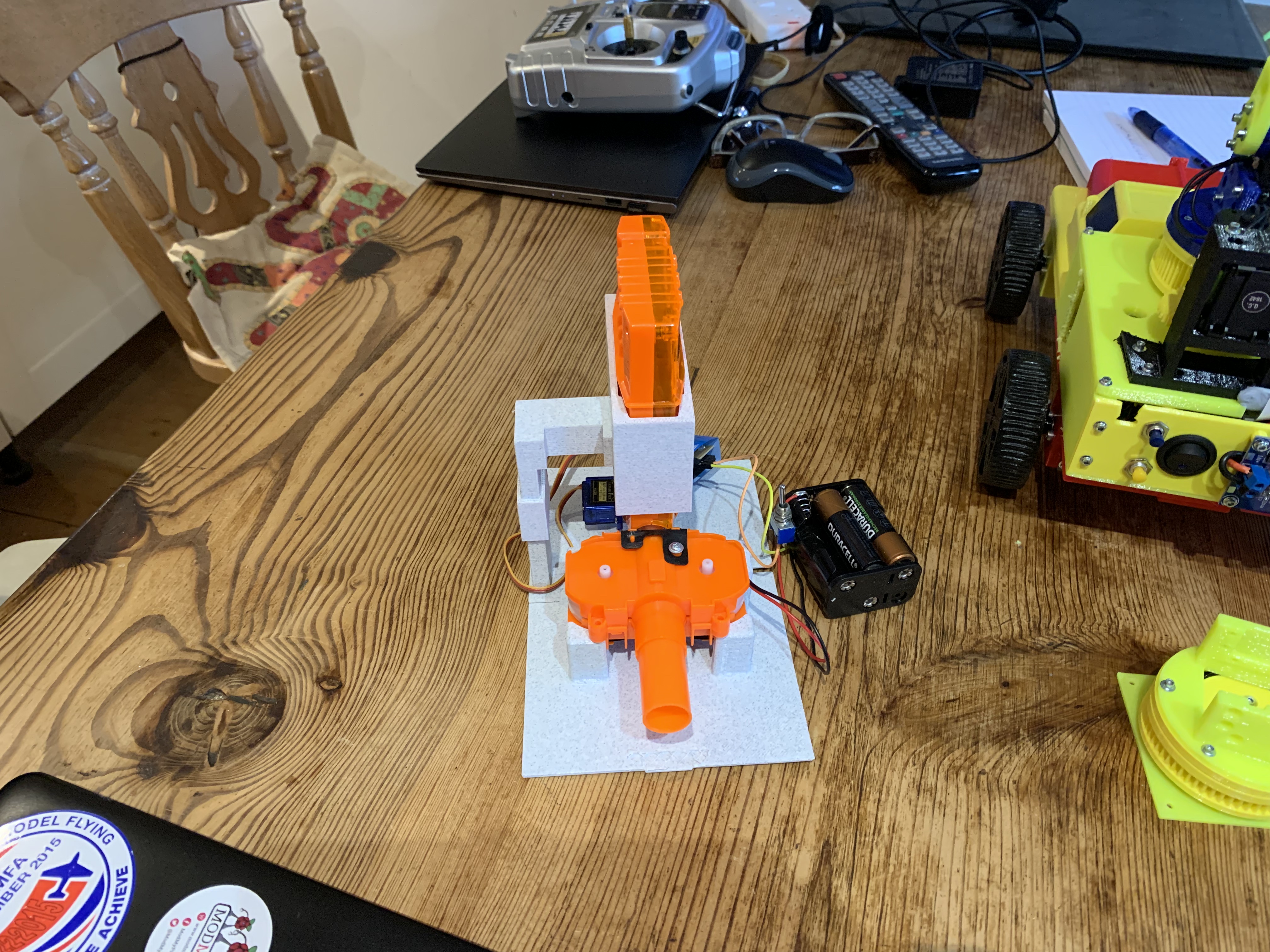
Still, onward, we have a chassis and some arms so time to play.


Sunday, June 12, 2022

Zyderbot Architecture

 Zyderbot is very modular and the parts have been assembled to work together around ideas put in place early on in the competition. This is a brief overview of what it comprises. 


The central chassis, as described in previous blogs. houses the controller Raspberry Pi and it is this which forms the central control and communication hub of the robot. 

A VNC connection to this Pi is used to connect to it from a laptop and programming is done using the Python IDE or Thonny. The controller Pi also runs the camera, support for which is built into the Pi.

The rest of the robot platform is modularised to provide dedicated functions, there are two groups, the main chassis controllers and the attachment controllers. As this is our first entry into PiWars, we've designed something which is reusable and the design and code is on Github. 

The main controller runs a command queue, onto which commands can be placed, either from an onboard file, as running a script, from the command line as direct input, or as a response from a separate controller, which in this case is either a Pico or an ESP32.

For autonomous processing, the controller reads a script file and runs commands to either take actions or invoke further autonomous actions, such as running a trough filling hopper or picking an apple. 

A motion command will be sent to the Motor Controller Pico which measures distance and actuates the four chassis motors. 

For Remote Control operation, an ESP32 is used with a PS3 handheld controller to submit commands to the controller, which are passed onto the Motor Controller, providing the necessary control.

For audio input, a separate Pico is used to listen on a microphone, interpret the audio signals it receives, and then pass these on to the command queue.

The Camera is invoked by commands to enable seeking and following operations, itself issuing commands back to the queue to act on received information.

The attachment controllers are there to enable easy integration between the chassis and the attachments, running all the attachment motors, servos and sensors so relieving the main controller of that burden and providing a division of labour.

For each PiWars challenge, an attachment is provided, to a standard mounting specification, power supplied from the batteries as a nominal 12V and communication to the Pi controller is over USB, which also supplies controller power an enables coding on the attachment controller from the central Pi.

There's a lot of code around this, as well as some direct handshake signals to get the timing right, but it's a good platform to take forward into future projects and competitions.

Monday, May 23, 2022

Using the remote

 With lots of challenging challenges, it has felt easy to ignore that the Farmyard Tours was to be remote control and not autonomous, so we needed a solution which was a bit more dextrous than a keyboard. Using a full RC set with adapters was always an option, but a more personal system was preferred and an almost universal games controller format was chosen. 


Could have been any brand, but it turned out as a low cost PS3 controller from a no-name Chinese source. As the main Pi controller just wanted a data feed it could translate, the interface chosen to the controller was Bluetooth run by a small ESP32 module dedicated to the communication. This was a lot less bother than direct comms and meant that the controller Pi wasn't cluttered with noisy code. Here is a larger dev board for testing, and mounted on a test chassis. The communication is via serial over USB and a simple handshaking option is used to request data from the PS3. 


One of the issues with this configuration is that when the controller times out and disconnects, the ESP32 code can't reconnect, so an extra pin was dedicated to reboot the ESP32 into connection mode again. 

Here's a brief video of the test chassis twirling in the arena..........and negotiating a bit of garden.


....and negotiating a bit of garden.


Thursday, May 19, 2022

A new chassis

So after lots of testing....well a bit anyway...we needed to build a new chassis, if only because we'd drilled so many holes in the old one! 

First make the battery holder which is also part of the suspension. Here it is.


Well that's spectacular isn't it. It's very basic, is made from a piece of acrylic tube, one end has a fixed plastic plug with a battery contact permanently attached and the other has a plastic spring holding the other contact in, which is held in place with a screw. The tube itself forms the central pivot of the suspension.

The two halves of the chassis were updated to accommodate the positioning of the camera as well as the main controller and attachment processors.

This is the rear subframe from below, the motors fixed in place either side of a tunnel which houses the battery tube. 

And a picture of the front subframe, housing motors, a camera and illumination LEDs, with the second half of the battery tunnel shown.

Putting them together, with an empty tube in the middle. The two subframes can rotate independently of each other around the battery tube. This isn't of much use in the arena challenges, but when negotiating the farm tour obstacle course it's expected to come into its own to keep the chassis stable and in contact with the ground.

As mentioned previously, part of the rebuild was to accommodate a camera.
The camera is mounted below the attachment deck of the chassis, the bolt holes for attachments can be see top left and right, and faces down and forward, looking at the arena surface ahead of the robot. The LEDs are there to ensure it has plenty of illumination for the camera and isn't dependent on ambient light, eliminating an uncertain variable.


Close-up of the two subframes partly rotated against each other to show the suspension in operation. Already, with only the motor, LEDs and camera fitted there are a lot of wires in this robot and cable management is important, hence the prepared holes in the subframes.

From the outset we wanted interchangeable wheels to adapt to the different challenges. These are 'arena' wheels with their adapters. The adapters were always part of the design as with so many different motor shaft attachments available we needed to be able to switch them without having to remake whole wheels.


Now it looks a lot more like something with the wheels attached and wires routed. The front chassis  mounts for attachments can be seen, and that growing wiring is getting some management..

And suddenly there's a wire explosion!!! At the rear (right) is the main power switch, and just ahead is the controller pi board mounted vertically. At the far side is the power regulator. Raw power from the batteries is delivered at around 11V and used by the attachments, the regulator ensures the pi is supplied with a healthy 5V. 
Nearest the camera is the motor control pico which receives commands from the controller and incorporates a LED to provide a simple status display. This connects to the controller via USB. 

And here is the assembled new chassis with the Hungry Cattle hopper attachment. 
There's a lot of parts to this but it does work very well. Only a short video of this chassis working but it gives an idea of the basics.


Next up a  blog giving a description of the architecture of these robots.