Saturday, January 29, 2022

S.L.A.M

Simultaneous Locating And Mapping summary 16/Jan/2022

Actually, there’s not a lot of mapping, as we build the arena, so we hopefully know where everything is, but locating the robot within the arena is a big deal in PiWars 2022 as there is a lot more stuff about than in 2021. 

General concept: stereo cameras and beacons.


Beacons

The logic chain ...

  • You need identifiable landmarks in a known location.
  • How do you pick them out from the background clutter? If you use LED beacons then you can drastically underexpose the image, leaving only the LEDS showing.
  • How do you identify them? Use different colours.
  • Why not a modulation? Because you have to do this fast on a moving platform, you can’t afford the time to observe the beacon over a time period to see changes.
  • What colours? Well, it turns out that the obvious RGB colours have a problem, which is that the Green is too close to the Blue for rapid distinguishing, so just Red and Blue then.
  • How high? First guess was on the ground with the cameras underslung (leaving the robot top completely clear for attachments). But what about the sheep and troughs obstructing the view, let alone attachments hanging down? So current guess is 110mm up. That means we can have the cameras on the back of the robot unobstructed.
  • What if that’s wrong? They are mounted on 8mm square section carbon fibre tube, so if we need them higher up, we just use longer tubes.
  • What kind of LEDs? First we chose RGB LEDs. This means that if we change our minds about colours we can just solder in some new resistors and get any colour we like. We started out with clear 5mm LEDs with 3D printed HD Glass diffusers, but why make work for yourself when you can get 10mm diffused LEDs?
  • How many LEDs? Given just two colours and four LEDs you get 16 combinations. Each arena wall has a maximum of seven LEDs (if you include the corners) so can then have a unique pattern of beacons. If we need each beacon to be unique in the whole arena we will have to go to three colours or five LEDs

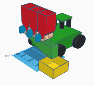
They are powered at 9V, so could use PP3s, hence the little box at the base


Beacon identification software

    First thought, use OpenCV for both image capture and processing. It’s a bit worrying that it takes 25 seconds to load (not to mention 5 hours to install), but runtime is lightning fast and the loading takes place before the timed run, so should not be a real problem. So we start with a pair of 640x480x3 RGB images (possibly on different computers) captured with OpenCV. 
    We can get 29 frames per second (FPS) capturing stereo pairs on a single computer (the Stereo Pi). However, it turns out that we can process them in a very basic way just with numpy and get a calculation ‘frame rate’ of 1880 FPS, so simple image processing has no real effect on performance. The killer is reliability.     OpenCV just doesn’t control the camera hardware properly. This means that every now and then the image goes green monochrome or the GStreamer is incorrectly invoked. Even after weeks of trying I cannot resolve this, so it’s PiCamera and NumPy for now.

Phase 1

The base image is 640 columns wide, 480 rows high, and with 3 colours (RGB)

Locating beacons
This is done by just looking for at least 5 consecutive bright columns in the image to make a column set.

Measuring the Angle

The dreadful barrel distortion of the lens is compensated for by a cosine formula determined experimentally from calibration images. This is then used to create a lookup table to convert the column number of the middle column to an angle, i.e. the bearing from the camera.

Locating LEDs

Look for at least 3 consecutive bright rows in a column set. Note that the LEDs are separated by quite thick separators so that they don’t run into one another in the image. Produces a set of rectangles in the image.

Determining the colours

Because we only have red and blue, we just sum those colours in an LED rectangle; if there’s more red than blue, it’s a red LED, otherwise it’s blue. Note that using OpenCV and YUV encoding we may be able to reliably distinguish green as well, but can’t do that currently.

Identifying the beacons

We have a database of beacons and their colour codes, so RBBR is a beacon with, from the top, Red, Blue, Blue, and Red, LEDs. The database records their location in arena coordinates (garage is 0,0)
The end result of Phase 1 is a set of beacon identifiers and angles. These are written to a database (currently on the PI Zero, but eventually will be on the central Pi)

Phase 2 - Getting a Fix

Choosing the bearings

From the bearings table we choose those ones to use. We want bearings of the same beacons from both cameras taken at the same time. From those we want the pair of beacons furthest apart to get the best angles, so from those beacons which occur in both images we choose the leftmost beacon and the rightmost beacon.

Calculating the position

This is some trigonometry, using the cosine rule and the sine rule. The result is the location of the beacons relative to the robot. Translating the co-ordinate systems we calculate the location of the robot relative to the arena.

Next ...

PID control of motors using the location delivered above (PID = Proportional Integral Derivative). Planned path will be a series of locations (arena x,y co-ordinates), plus angle (orientation of the robot relative to the arena).

Performance

Cameras

The basic picamera is a very cheap device using a tiny plastic lens. It has bad barrel distortion and you might think that we have to do a complex correction grid, but actually, because of the very specific use case a fairly straightforward correction does the job. So long as the camera sensor is absolutely vertical and at exactly the same height as the middle of the LED beacon the barrel distortion above and below the middle doesn’t affect it.

Timing

Obviously the calculation of location from a stereo pair of images taken from a moving vehicle is dependent on the two images being taken at the same time. Paula has done a study of synchronisation procedures which should solve the problem of clock differences. Because picamera capture cannot be directly triggered (you are picking up frames from a continuous video stream) some more work is required to convert clock synchronicity into camera synchronicity.

Basic Capture Frame Rate

Stereo Pi (= Pi 3), single camera, RGB, picamera
straight capture:  1.7 fps 
capture using video port:  5.0 fps

Stereo Pi (= Pi 3), camera pair, BGR, OpenCV 
capture using video port:  29.3 fps

Single Pi Zero 2 W, single camera, BGR, OpenCV 
capture using video port:  61.7 fps

Geometry Frame Rate

from column compute location
using numpy  1880 fps

Accuracy

This is the big one. To avoid the need for supplementary location systems we need to get pretty close to 1mm accuracy. 10mm might be OK, but 100mm would be a waste of time. At present we are not near that, but there is time for more optimisation and calibration.

Friday, January 14, 2022

Enter Turbo-shepherd

 The Shepherds Pi challenge has been looked at a bit, but after a few trial runs with wooden paddles and cardboard sheep, it was obvious a bit of extra manipulation was going to be necessary to do it quickly, and not just shove the sheep and wolves around. Enter a pair or arms to help.


The arms are articulated to fold flat to the chassis, and then when folded out, articulate half way along to allow nudging, flipping and to form a funnel. Each arm can also be raised and lowered to be lifted out of the way quickly to provide easier chassis manoeuvring. Building arms this way also provides a mechanism to provide for gate opening and closing.

The first prototype for this has been built but currently a bit slow for competition, but will be ok for testing the concept and planning movements.


No peace for the busy, the basic Hungry Cattle hopper feeders work but when a side funnel is fitted, the rate of dispensing goes down and even stops unless the funnel has a steep angle. Experiments with this has set a good angle at 40 degrees or more which raises the hopper height by at least 100mm, making the whole robot approach 300mm height. This is ok in the rules but there will be a bit of weight in the feed so may make the chassis unstable at speed.

So a new concept is under review, rotating hoppers which sit in a carrousel and rotate out over the trough to be filled.


In the barn/filling position, the hoppers sit inside the footprint of the chassis, openings pointing upwards.


When alongside the trough, the carousel rotates to position a hopper over the trough where it empties and the chassis them moves on to the next trough. While the chassis is moving, the carrousel rotates again to position the next hopper, ready to empty in the next trough. Returning to the barn, the carousel rotates back to the starting position.

Because the hoppers now have larger openings, its expected that the rate of discharge will be faster than the previous design, and will be more reliable, there being no closing mechanism to jam. Placing the carousel like this also gives a clearer view for the stereo vision system to navigate.

That's all for now, more experiments to do, bits to make and robots to crash!!!


Wednesday, January 12, 2022

After the holidays

 While we've all been paddling furiously beneath the water, there isn't a lot to show for the last few weeks.  One under the cover development is the synchronisation of the stereo vision system, which is combining the output from two cameras connected to two independent computers. 

I've slightly edited this to fit, but this is the detailed work team member Paula did as the solution. I'll leave most of it as Paula's own words.


Executive Summary:

Over the Christmas period I assembled the hardware and then commenced testing the accuracy of a

Raspberry pi providing a hardware pulse per second, to try to achieve a accuracy of under a

millisecond to enable a pair of raspberry pi zeros that each use a camera to create stereo pairs for

range detection. This was achieved using the pps-gpio overlay module. In the process I discovered

that accuracy can be maintained between reboot or shutdown by using the appropriate driftfile or

adjtime so long as the overlying daemon processes is still enabled.

Object:

To find a way of synchronising external Pi zeros to a hardwire pulse.

Discussion:

A trawl of the internet found that we could use a pulse per second (PPS) provided in the distribution

overlays.

Method:

1: Configure a raspberry pi as a source using a gps receiver dongle to give the 1PPS on a GPIO pin.

2: find software resources to measure the uncertainty.

3: train internal clock using supplied network time protocol with the addition of ntp-tools

4: compare results with both GPS and a RTC chip ds1307

5: report findings, recommendations and conclusions.

Hardware used.

OS Buster 10.5.63 on raspberry pi 2 model A

Real Time Clock using ds1307.

GPS module MTK3339 as source for PPS on pin 4

Important considerations.

The pulse is measured as a leading rising edge on the pin

Temperature is held fairly constant so that drift of internal clock is minimal.

Unfortunately we cannot control the pressure, but for the period of use in the arena ,that we plan, this

may be considered negligible .

configuring the ntpd.conf is quite confusing and detailed to get the best performance.

use a static ip address as using dhcp can lead to higher jitter.

Software changes used

sudo apt-get update

sudo apt dist-upgrade && sudo apt rpi-update

Only enable the firmware update NOT a full update to latest beta os

sudo reboot

sudo apt install pps-tools libcap-dev -y


Optional for Real Time Clock(RTC) module only

enable i2c in


Preferences > Raspberry Pi Configuration > Interfaces

sudo apt install i2c-tools -y

sudo nano /boot/config.txt - Add dtoverlay=i2c-rtc,ds1307 on a new line,

check that the # is removed from dtparam=i2c_arm=on

save and close


Optional for GPS display of satellites etc. only

Preferences > Raspberry Pi Configuration > Interfaces

disable console

sudo apt install gpsd gpsd-clients python-gps -y

Now add the following altering gpiopin to suit.

sudo nano /boot/config.txt - Add dtoverlay=pps-gpio,gpiopin=4 on a new line,

save and close


Now type

sudo echo “pps-gpio” >>/etc/modules


Now reboot by typing

reboot


On restart check that the pps is loaded and being received (once connected and source started).

dmesg | egrep pps

or to see them

sudo ppstest /dev/pps0 ctrl+c to quit

We now have a pulse to align to the internal clock


How does a raspberry pi find the time without an internal real time clock?

In the current kernel on booting a RPi the date and time are taken from a file /etc/fake-hwclock.data

and incremented at regular hourly intervals. If and only if your device is able to receive valid time

sources e.g. Network Time Protocol(NTP) or the newer CHRONYD etc., then internal time is

corrected on receipt of a valid string and continually used until you reboot or shutdown, hence it can

perturb any statistics unless you create a driftfile more later. Incidentally in the case of the Pico, I

believe that there is no saved file hence it starts from a fixed date.

Even if we have no external source we need to define one in ntp.conf and mark it with prefer for the

PPS to work(see below)

Processes:

1) from GPS hardware 1PPS periodic > pin 4 > NTPD/CHRONYD

2) from GPS software NMEA messages periodic > GPSD

3) from GPSD in Shared Memory > NTPD

4) from NTP servers periodic > NTPD

5) from RTC on demand


A) Using the Network time protocol daemon(NTPD) is very confusing in the beginning, but

perseverance is required. Edit the default /etc/ntp.conf file as follows:

# /etc/ntp.conf, configuration for ntpd; see ntp.conf(5) for help

driftfile /var/lib/ntp/ntp.drift

# Enable this if you want statistics to be logged.

statsdir /var/log/ntpstats/

statistics loopstats peerstats clockstats

filegen loopstats file loopstats type day enable

filegen peerstats file peerstats type day enable

filegen clockstats file clockstats type day enable

# You do need to talk to an NTP server or two (or three).

#server ntp.your-provider.example

# pool.ntp.org maps to about 1000 low-stratum NTP servers. Your server will

# pick a different set every time it starts up. Please consider joining the

# pool: <http://www.pool.ntp.org/join.html>

server 0.debian.pool.ntp.org iburst prefer

#server 1.debian.pool.ntp.org iburst

#server 2.debian.pool.ntp.org iburst

#server 3.debian.pool.ntp.org iburst

# Server from shared memory provided by gpsd PLT

#server 127.127.28.0 minpoll 4 maxpoll 4 prefer

#server 127.127.28.0 minpoll 4 maxpoll 4

### Server from Microstack PPS on gpio pin 4 PLT

server 127.127.22.0 minpoll 4 maxpoll 4

fudge 127.127.22.0 refid kPPS

##fudge 127.127.22.0 flag3 1

#next line just so we can process the nmea for string offset note invert value

from ntpq PLT

server 127.127.28.0 minpoll 4 maxpoll 4 iburst

fudge 127.127.28.0 time1 +0.320 refid GPSD flag 1 1 stratum 6

#### end of changes PLT

# UK pool servers

pool uk.pool.ntp.org minpoll 10 iburst prefer

# Access control configuration; see /usr/share/doc/ntp-doc/html/accopt.html for

# details. The web page <http://support.ntp.org/bin/view/Support/

AccessRestrictions>

# might also be helpful.

#

# Note that "restrict" applies to both servers and clients, so a configuration

# that might be intended to block requests from certain clients could also end

# up blocking replies from your own upstream servers.

# By default, exchange time with everybody, but don't allow configuration.

restrict -4 default kod notrap nomodify nopeer noquery

restrict -6 default kod notrap nomodify nopeer noquery

# Local users may interrogate the ntp server more closely.

restrict 127.0.0.1

restrict ::1

# Clients from this (example!) subnet have unlimited access, but only if

# cryptographically authenticated.

#restrict 192.168.123.0 mask 255.255.255.0 notrust

# If you want to provide time to your local subnet, change the next line.

# (Again, the address is an example only.)

#broadcast 192.168.123.255

broadcast 192.168.1.255

# If you want to listen to time broadcasts on your local subnet, de-comment the

# next lines. Please do this only if you trust everybody on the network!

#disable auth

#broadcastclient

#end of file /etc/ntp.conf

B: As Real Time Clocks are not provided on the board of raspberry pi’s

we need to add as in the options above, but to read and set we use

an old tool hwclock as I find the latest tool timedatectl a pain.

to set the time for the first time use:

1: sudo hwclock -w this will take the current time from the Rpi>RTC

or 2: timedatectl set-time “yyyy-mm-dd hh:mm:ss”

To read use

1: sudo hwclock -r

or 2: timedatectl status

you have to fiddle about with hwclock-set

sudo nano /lib/udev/hwclock-set

comment out the following lines to look like:

#if [ -e /run/systemd/system ] ; then

# exit 0

#fi

save and return

Now we can compare results, but for more consult the spell foundry webpage above.

To casually look at the RTC performance use

timedatectl status

But we really need to make the system learn the drift characteristics of the RTC clock to do this we

run the system for days and be connected to the internet, then use the /etc/adjtime file to store the

results it requires a minimum of 4 hours before it records any value!

use periodically over a few days

sudo hwclock —w —-update-drift -v

There are other parameters we need to change if running independently of the internet, that are

outlined on the reference below.

Results:

After an hour I get these from /var/log/ntpstats/loopstats


Which is as good as we can get with a pi and GPS with limited view of satellites. Note: the vacillating

-+ of the accuracy reading in seconds indicates a narrowing of the measurements, further narrowing

will take many hours.


and using gps tool

gpsmon -n (exit with q then return)


Conclusions:

The internal timing on a raspberry pi are not sufficient to maintain the needed 1 millisecond

accuracy for our purposes.Just the change in ambient temperature or pressure is enough to thwart

our goal in stand alone mode, the use of the ability to use a 1PPS seems to be the way forward. The

results speak for themselves when compared with both the raw data from either NTP and GPS,

disciplining the local clock drifts before we launch would be sensible to maintain the accuracy

required by using the above techniques.


Further reading:

References:

1: David Taylor’s page https://www.satsignal.eu/ntp/Raspberry-Pi-NTP.html

and additions from corespondents on that site.

2: John Watkins’s spell foundry on https://spellfoundry.com/docs/setting-up-the-real-time-clock-onraspbian-

jessie-or-stretch/

802.1AS - Timing and Synchronisation https://www.ieee802.org/1/pages/802.1as.html

Paula Taylor 2022109

Friday, December 17, 2021

Reporting from the cabin 2


The meeting was an opportunity to put some plans and dates in place, so we know what dates we need to get things working by, ready for testing, and of course ready for videoing.

1. Finish research and agree approach by end of January

2. Complete robot component design by end of February

3. Complete robot construction by end of May

4. Complete testing and ready for video for end of June.

Seems plenty of time but then we all have other projects we're working on.

Having made some sheep, we played around with how we could gather them in and move them about, mainly with a few bits of wood and patting the cardboard about, and found we could get quite a lot done that way. Scaling this up to a practical robot attachment we got an idea we could make and test.


This is very much in keeping with what we can make so prototypes will be constructed to try out for next time.

In keeping with the Shepherds Pi challenge, we've also acquired a whistle and microphone for issuing commands to 'rover', so it's likely a fair bit of annoyance will be caused with loud whistles for testing.


And just to keep the theme going, a shepherds crook which might form part of a gate opener and sheep prodder when we have a better idea of what is needed there.


In a previous blog, we had pictures of the cattle feeding hoppers in design and now they have become reality, though still in need of a connecting bracket to the mounting plate. 


We still need to make a funnel to direct the feed sideways to the trough, but this part is well underway for having it's first solution. A second solution is not out of the question if it's better. Quite obviously we need a cable management solution to!

That's it for now,  a break until the new year though I'm sure we'll all have designed or made something in between, and videos of mass hopper emptying as well sheep herders to look forward to. We'll stop using the pretty yellow and green plastic as well, looks too good for prototypes so back to more boring colours, we'll bring them out again for final construction.


Reporting from the cabin 1

We had another show and tell update meeting to report progress and lots came out of this, so much so that we have two blog posts to report it all, otherwise it gets very long and boring! 

First off is the new vision system. We had originally been working with a borrowed StereoPi system but our chassis master wanted better performance and started work with OpenCV on the new Raspbery Pi Zero 2, the technical details recounted in our last blog post. Here are a couple of pictures of the new camera solution.


Two Pi Zero 2's with two cameras, they've been setup at 65mm separation to facilitate usage with VR if we want to go down that route at sometime. Next up is time synchronisation and distance measurement based on the stereo image.

On a more prosaic subject, we looked at some more cardboard models of trees and sheep.


It makes for a very useful exercise to actually build the challenge props and look at them instead of theorising online, and so we had some cardboard sheep made up which we pushed around, knocked over picked up etc to see how they could be moved around. Similarly, we looked at the 'wolf' pieces and what they would be like to operate around, how easy to move or pick up.

This led to the decision to use balsawood to construct accurate 'sheep' to which we will add separate decoration in the future.


It is a simple thing but just getting it right will make the challenge easier to design for and prototype.

The 'apples' on the tree had already been designed, they're polystyrene balls, but a bit of thought for attachment (and detachment) was needed. We're attaching via magnets, which while apparently straightforward threw up a set of issues. First off, they have to be strong enough to hold the apple easily, this also helps with setup between runs so that attaching apples is easy.


Secondly, they have to be detachable, obvious but the more attachable it is, the less detachable it becomes!!! Silly observation perhaps, but there is definitely a balance to be found, we did find with some quite small magnets that the cardboard tree was easily pulled over, and when the apple came free, sprung back dislodging other apples. A cardboard tree isn't necessarily the best subject so a thin MDF one will be made for the next tests.

The attachment fitting for the chassis had been decided upon at the last meeting, and a trial plate made to test it. Unfortunately, the measurements for this were off and a second had to be made.


The main chassis fixings are on a 80mm grid for M4 bolts, with the outside dimensions 100mm. Onto this are moulded four lugs to fit the attachment securely, together with four raised supports for a PCB (dimensioned for a .254mm pcb matrix board) to be fitted.


This is the mounting fitted to the chassis. Not the most exciting item but essential.

That's enough for this entry, see the second blog entry for what else we got up to.


Wednesday, December 15, 2021

An OpenCV story

 Our chassis builder was determined to get OpenCV working on the latest Raspberry Pi platform for our entry, but it wasn't as straight forward as a quick download...................

Installing OpenCV on Raspberry Pi Zero 2 W

A tale with a moral

I have been interested in using OpenCV for years, but the driving force of need was never strong enough to overcome the obstacles. For example, my bomb disposal robot needed to detect the bomb. I scoured the Internet for instruction on installing OpenCV, but in the time it took to try and fail a few times I was able to implement Canny edge detection myself, and it worked fine for that purpose.

Then came Pi Wars 2022. Suddenly the goalposts had moved. Whereas the bomb disposal robot, which moved slowly in any case, was happy with two detections a second, I reckoned that our Pi Wars 2022 robot would need at least twenty, and preferably forty. So, back to the Internet.

If you type “install opencv on raspberry pi” into Google, you get 839,000 results, and I'm here to tell you that the most common single category is someone who has read how to do it and is passing it on without actually trying it themselves. Why do they do it? It just makes more crud to wade through. The next category is people who have tried it and got it to work on a very specific configuration, but don't explain fully what that configuration was, so you can't tell if it's applicable. One common thread is that a full install from scratch can take days and is fraught with peril. I asked on Discord for a prepared disk image without success. In total, over time, looking for shortcuts, I probably spent several days not installing OpenCV

Eventually I gave up on shortcuts, bit the bullet, and found a recipe for doing it the hard way. https://pimylifeup.com/raspberry-pi-opencv/ It was marked “beginner” which turned out to be a bit optimistic, but basically it worked!

A few prerequisites may be missing, so I added the following:

sudo apt-get install libatlas-base-dev

sudo apt-get install libjasper-dev

sudo apt-get install libqtgui4

sudo apt-get install libqt4-test

sudo apt-get install libgtk2.0-dev

sudo apt-get install pkg-config

sudo apt install libopenblas-base

sudo apt install libopenblas-dev

sudo apt install liblapacke-dev

If they are already there, running the install will do no harm.

Anyway: I now have OpenCV working on a variety of Pis in the sense that all the facilities in there that I think I need are present. I have made the disk images available on Google Drive if anyone wants to save effort, but I would encourage people to do it themselves.

Moral: sometimes the hard way is the best way.

Colin Walls
05/Dec/2021


P.S. The Pi Camera

Anyone used to SLRs will find the Pi camera hard to understand, particularly as it is on the end of a long chain of hardware and software, all trying to be helpful, but obscuring what is really happening, so …

There is no diaphragm, so you can't adjust the F stop. 'ISO' affects analogue gain and has no effect on raw sensor sensitivity. The focus is factory set (supposedly to 2m - infinity) and glued into place. There is no shutter, so light is hitting the sensor at all times. The sequence of zeroing, waiting, and reading pixel rows is roughly equivalent to a rolling shutter though, and the waiting period is roughly equivalent to shutter speed.

It is a video camera, there are no stills in the conventional sense. When you 'capture' an image what is really happening is that you get given the last video frame that the camera happened to produce. This means that you can't synchronise two cameras by 'capturing' an image at the same instant. This is why frame rate is crucial, because (assuming a 30fps rate, for example) any frame could be up to 1/30 second old when you get it, and the two cameras could be up to 1/30 second different in time of capture.

One thing common to nearly all digital cameras is that each pixel captures only one colour, so the true resolution is ¼ what you think it is, as other values are interpolated. This means that the ¼ 'maximum resolution' resolution has the special quality of matching the natural binning of the Bayer quartets in the sensor and involves a lot less processing. For the Pi camera V1 this 'sweet spot' is 1296 x 972. For the V2 it is 1640 x 1232

If you want to know more, read

https://picamera.readthedocs.io/en/release-1.13/fov.html

Wednesday, December 1, 2021

Always something new

 While we're all busy with different things, somehow we get new ideas for PiWars challenges. So we have a new Hungry Cattle hopper design, this time both a measure, and also a funnel to direct the feed to the trough.

This design is to have a single hopper dispensing a measured amount of feed only into the trough. The main hopper is 122 x 100 x 104mm and the cylinder, which can rotate through 360 degrees, is 62 x 100mm long.  

In addition to considering a new hopper, there's also the idea of a side funnel to direct the feed independent of the hopper position. 


With this addition, the current chassis can drive up alongside the trough, dispense the feed, and then drive on saving time. Using the central front hopper only, the chassis has to drive up to the trough, dispense the feed, and then manoeuvre away from the trough, all of which is extra navigation.

Thinking of a decoration for the arena, instead of just plain cardboard, or MDF, a colour scheme. 

This looks a bit more field like, as well as having the useful 250mm grid lines for laying out the challenges. Not sure about having muddy pools yet!

When it comes to thinking about a challenge, we can be very analytical, so here are a few diagrams ahead of our full apple picker design.
This is a chassis and attachment volume model showing the extents that a any given design can occupy.

Applying this to the apple tree, we can view the approach distances and develop a strategy.

From this we can then design the apple picker to fit the strategy, QED :) 


We did lots of clever software work as well, write up on that next time. 


Tuesday, November 23, 2021

When will we five meet again

 Lots of things happen when we get together, lots of ideas passed around and a few demonstrations. 

First up was the Hungry Cattle hopper and filler. This had been interrupted by a dodgy 3D printer hotend, but soon fixed and construction completed. 


The wooden bit is just for demonstration. It was duly loaded with the cheapest rice we could find and tested out. This is a video of a couple of runs, the first in real time, the second in slow motion.

Generally very happy with this, but improvements to be made. One big one is to automatically close the hopper after emptying, to prevent the accident had later, of pouring rice into an open hopper and subsequently all over the bench and floor, important for when we do the real run as well so that the robot is ready for refill as soon as possible. Another is to add indicator lights to show open and closed statuses, this may be just a physical switch changing coloured LEDs but giving feedback on status. The final change would be the use of a centralised hopper below the three currently planned so that the robot only has to position one feed outlet.


This layout would also help with detecting trough position to ensure that the robot releases when the hopper is above the trough. This is getting to be quite a big attachment!

Next up we had a look at the Nature's Bounty challenge. We had already had a look individually at a solution to this challenge but now was the opportunity to collectively look at the size of robot and the size of the tree.

A demo of a trough to hold collected apples in was examined and the ease, or otherwise of catching and storing apples soon became interesting. The apples themselves are also part of the problem, and for the time being in the project, they are polystyrene balls. They are lightweight, can be gripped from any angle and don't bounce much when dropped, so are easier to control. The plan is to colour these and attach them to the tree using steel washers and magnets. So here's a clutch of 'apples' in a trough and cue lots of dropping apples off the tree.


Out of this came a new solution, putting the trough underneath the robot.


Not sure if this will take off yet, but it does fix a few problems, and unloading might need a door and drawer at the rear!!!

The strategy of storing picked apples now having direction, the approach to actually picking the apples was looked at, also lots of fun, each of us pretending to be robots picking apples and how they would go about it.

Three obvious approaches to the tree were looked at as follows. 

This one doesn't take much imagination, drive up to the tree branches at 90 degrees and pick. Being at right-angle to the branch means the apples are in an easy position to pick, and the robot chassis can be aligned easily.


This second one goes in diagonally. This is much more difficult as it needs to approach the tree at an angle meaning more complex navigation, and the robot would need to be aligned to the tree axis. But it does allow for the possibility of picking two branches without relocating the robot chassis, which would make it faster.

Picking 'end on' to the tree branches lends itself to removing one dimension from the picker, that of moving left or right, which the other positions required, as well as in/out and up/down. It is difficult to achieve within the competitions dimensions rules but that's part of being inventive. Someone building a robot with mecanum wheels might even be able to drive in a circle, picking as they go.

No final design was agreed upon, someone taking away the task to draw up the picker configuration for next time. 

We had a quick demonstration of the StereoPi in operation mounted on the robot chassis, it looks good, but the demands of the chassis designer are high and they aren't satisfied. More on this another day.

We talked about the first challenge Shepherds Pi, but this is a real agility test for a robot, and we decided to leave it to another day when the chassis is a bit more advanced and we can experiment with moving around the arena in remote control, rather than just theorise about solutions. 

The fourth challenge, Farmyard Tours, got lots of ideas, and we agreed to go off and submit them as emails to gather them all together, it's unlikely that much will be said about these here for the time being unless we can't do them!!!!

Finally, a key piece of design was agreed upon, the attachment mounting. This is important
so we all know what we are designing to, and basically its four mounting holes on an 80mm grid on an 90mm plate.


The lugs on top aren't part of the specification, they're just there to aid mounting an attachment, in this case the Hungry Cattle hoppers.

And that's it for another week, the hopper controller has already been built on Arduino, but needs migrating to Pico, we're all getting back together to see the apple picker design after the next Raspberry Jam, and the next meeting will have a run through of the Shepherds Pi challenge, probably in slow motion as none of us are RC experts!!!